Catia Sheet Metal Hopper

Catia V5 Tutorial Surfacic Hopper Sheetmetal Workbench Youtube


Toby S Tech Talk Episode 078 Sheet Metal Hopper And Solidworks Inspection

Solidworks Tutorial Sheet Metal Drawings Youtube Sheet Metal Drawing Solidworks Tutorial Sheet Metal

Solidworks Sheet Metal Desenare Solidworks Sheet Metal Sheet Metal Drawing Sheet Metal Sheet Metal Work

Solidworks Sheet Metal Exercise Basics Youtube Sheet Metal Sheet Metal Drawing Solidworks

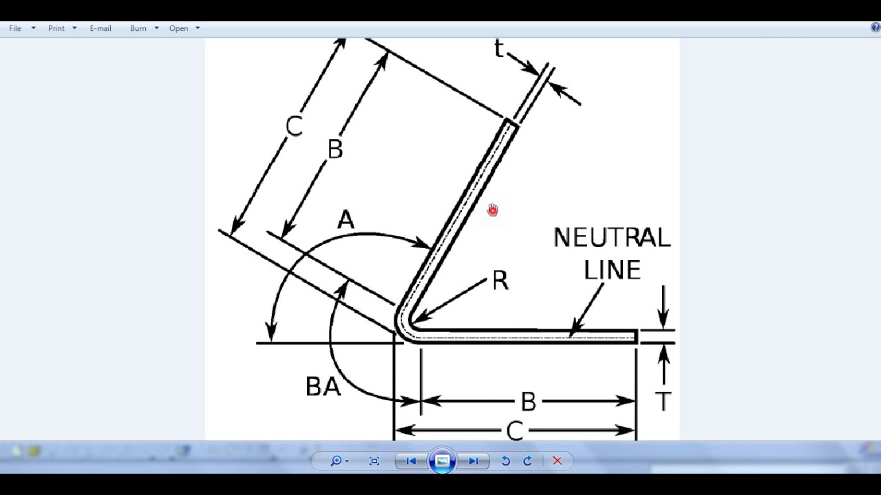
It is also the line from which the part unfolds.
Catia sheet metal hopper.

Pin On 3d Modeling Solidworks

How I Successfuly Organized My Very Own Sheet Metal 9d Drawings Pdf Sheet Metal 9d Drawings Pdf Sheet Metal Drawing Sheet Metal Drawing Book Pdf

Catia Sheetmetal Tutorial In Hindi Hooper Catia V5 R20 Hooper In Sheet Metal Youtube

Catia Generative Sheet Metal Design Rolled Walls Toolbar Youtube

3d Modeling Practice 698 Studycadcam In 2020 Solidworks Sheet Metal Drawing Industrial Design Sketch

Solidworks Tutorial Sketch Sheet Metal Screw In Solidworks Youtube Solidworks Tutorial Solidworks Tool Storage Diy

Pin On Autocad

Detailed Assembly Drawing Buscar Con Google Mechanical Engineering Design Mechanical Design Solidworks Tutorial

Solidworks Tutorial 122 Sheet Metal Hopper In Solidworks By Solidworks Easy Design Youtube

Pin On Solidworks

Youtube Solidworks Tutorial Solidworks Metal Box
Surfacic Hooper Canonic Hooper Rolled Wall Catia V5 Youtube

Catia V5 Tutorial Flanged Cut Out Stamp Sheetmetal Workbench Youtube

Solidworks Tutorial 160 How To Design A Single Clutch Plate Assembly In In 2020 Solidworks Tutorial Solidworks Mechanical Design

Lindy Hopper Adli Kullanicinin Www Studycadcam Com Panosundaki Pin Cizim Resim Teknik

How To Use Symmetry Constraint In Catia V5 Was Explained In This Article Symmetry Being Used Explained

Oblique Cone Off Centre Cone Radial Line Method Sheet Metal Drawing Sheet Metal Fabrication Sheet Metal Work
Catia V5 V6 Tutorial Sheet Metal Design Tutorial Part 02 Design Tutorials Metal Design Tutorial
Https Encrypted Tbn0 Gstatic Com Images Q Tbn 3aand9gct3zfazig75npdzpw Xd R1gzsyacdxiq4uba7vtl4pdytnncyc Usqp Cau

Catia V5 V6 Tutorial Batman Blade Design Tutorial Batman Design

Pin On Mechanical Engineering

Catia V5 Basic Beginner Tutorial 1 Catia V5 Sketcher Tutorial Tutorial Mechanical Design Basic

Pin On Cad

Solidworks Tutorial For Beginners Exercise 60 Youtube Solidworks Tutorial Solidworks Tutorial
Source : pinterest.com
